| | | |
Tech Design.....
___________________________
Correcting acoustic center offsets in dipole speakers...
The misalignment of the AC's results in a tilting of the polar response
downward and as the frequency increases the main lobe of the response
becomes narrower. The the AC misalignment is corrected, the main lobe
is aligned with the design axis.
Now let us consider a similar situation between a woofer and a midrange
of a 3-way conventional speaker. The situation is shown schematically in
Figure 2. We shall consider a system with a 141 Hz crossover and a
woofer to midrange separation of 2 feet. At 141 Hz the wave length is 8
feet so the driver separation is only 1/4 wave length. We shall also
exaggerate the offset, d, for reasons which will become apparent later, as
8 inches. The polar response at the crossover frequency of 141 Hz and a
distance of 3 meters is shown in Figure 3. The red curve is with the
offset corrected and the green is with no correction. As you can see
there is little effect on the polar response with only very small,
insignificant tilt. The 8" offset corresponds to a phase error of 30 degrees
at the crossover frequency. With an LR4 crossover a 30 degree phase
error result sin a -0.3 dB error in the on axis response. This is apparent in
Figure 3 along the horizontal axis. The same can not be said for other
types of crossovers. For example, for Butterworth crossover, where the
intended phase difference between sources is 90 degrees, a 30 degree
error would result in either a -3dB or +1.75 dB error on axis. Thus the
wisdom of using an "in phase" crossover is apparent. There is little
reason to make any effort to correct for this offset with an LR4
crossover (or any order "in phase" crossover for that matter) when the
crossover frequency is low, or when the driver separation and the offset
is significantly less than a wave length at the crossover frequency.
However, if it is desired to dot the i's and cross the t's it certainly doesn't
hurt to compensate for the delay, other than the added complexity of the
crossover.
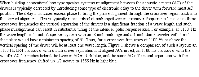
Figure 1. Polar response for
conventional speaker with
driver acoustic centers
aligned (red) and offset 1.5".
Driver separation is 6".
Crossover frequency = 1100
Hz for the red and dark blue
traces and 1550 for the light
blue trace.
conventional speaker with
driver acoustic centers
aligned (red) and offset 1.5".
Driver separation is 6".
Crossover frequency = 1100
Hz for the red and dark blue
traces and 1550 for the light
blue trace.
Conventional
Speakers
Speakers
Figure 2. Schematic representation of a conventional
speaker with woofer and midrange separated by a distance,
d, and off set acoustic centers.
speaker with woofer and midrange separated by a distance,
d, and off set acoustic centers.
Figure 3. Polar response for the conditions of
Figure 2 where d = 2 feet and the AC offset =
8 inches. Red, with offset correction; Green,
without offset correction
Figure 2 where d = 2 feet and the AC offset =
8 inches. Red, with offset correction; Green,
without offset correction
Dipole midrange and
woofer
woofer
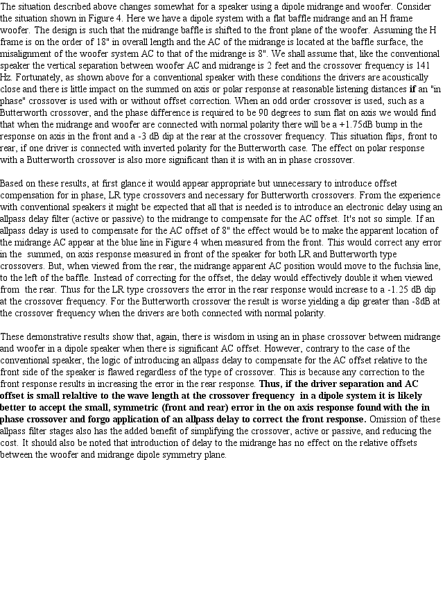
Figure 4. Speaker system using flat baffle dipole midrange with H-frame dipole woofer system. Baffle aligned to front plane of
H-frame resulting is significant driver AC misalignment.
H-frame resulting is significant driver AC misalignment.
Solutions to the
problem
problem
The solution to the problem, if you must retain a dipole woofer system, is to either uses a flat baffle woofer system or to align the
midrange baffle with the woofer system, as shown in Figure 5. The resulting AC alignment would result in no errors for any type
crossover. The trade off of figure 5 is the potential for diffraction and reflection from the top, front side of the woofer H-frame
directed towards the listener. However, the dipole radiation patterns tends to minimize this and if required acoustic damping material
could be applied to the surface.
Figure 5. Aligning the woofer and midrange dipole symmetry planes.
Cardioid and U-frame
woofers
woofers
If you are not fixed on the implementation of
a dipole woofer system a solution to the AC
offset problem can be found in the
application of cardioid or U-frame woofer
systems. Figure 6 shows a speaker system
using a cardioid or U-frame woofer system.
Where as the AC of the H-frame dipole is
located at the center of the H-frame the AC
of a U-frame or cardioid woofer system is
essentially located at the front plane of the
woofer. Thus the ACs are essentially
aligned when the midrange baffle is aligned
with the front of the woofer enclosure. Any
remaining offset is very small compared to
the wave length at the crossover point
resulting in insignificant errors in the front on
axis response regardless of the crossover
type. To the rear the result is inconsequential
due to the transition from dipole to cardioid.
However, this transition is best handled using
an in phase crossover. Since the rear
response ceases to be a factor, allpass
delays, while unnecessary, can again be
applied to compensate any residual offset, if
desired.
Figure 6. Speaker system with dipole midrange and cardioid woofer system.
In conclusion it is apparent that the conventional wisdom of correcting AC offsets using allpass delays or other means of introducing
excess phase in the crossover, as applied to box type direct radiator speakers, is flawed when applied to speaker systems employing
multiple dipole sources. This is because the offset of source 1 relative to source 2 reverses as we move from the front side of the
dipole speaker to the rear side. If the offset is X cm from the front, it is -X cm from the rear. Thus the delay compensation, while the
same magnitude, would have to be applied to the 2nd source rather than the 1st, or vice versa, situations which can not exist
simultaneously. Application of a delay will alway introduce greater error to the rear response if it corrects the misalignment relative to
the front of the speaker. The only correct solution is to physical align the AC of the two dipole sources. Otherwise it would appear
better use an in phase type crossover when the wave length at the crossover frequency is large relative to the AC offset and source
separation, and accept the small, symmetric front and rear errors. In reality, under these conditions the errors introduced either with,
or without the presence of the delay circuits is likely to have no audible consequences. This further suggests that introduction of delay
circuits in such application only introduces greater, unnecessary complexity and cost.
By contrast, if a cardioid or U-frame woofer system is employed, allpass delays can be used to correct the AC offset between the
cardioid woofer and dipole midrange since the rear response ceases to be an issue. However, with an in phase crossover, and even
with a Butterworth type crossover, the small offsets encountered relative the wave length at the crossover typically will not require any
such correction.
Closing
Rremarks
Rremarks